Ferrum OOR & HYPSOS: Compact, Powerful, Brilliant! - Review and Measurements
Introduction
The Ferrum OOR is quite a unique amplifier, moving away from both the IC opamp based designs of many budget amplifiers, and also the simpler topologies of many discrete amplifiers, instead offering a discrete opamp-based topology, packing an enormous amount of power into a small package, with excellent performance on top.
Ferrum Oor Desktop Headphone Amplifier
$1,995.00
Design
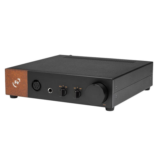
The OOR packs quite a few design aspects not seen almost anywhere else, both inside and outside the box. The most eye-catching of which is the square within which the Ferrum ‘Fe’ logo is set, sporting a textured brown finish thanks to the corten steel this piece is made from. Corten steel, also known as ‘weathering steel’ is a metal specifically intended to rust rapidly and produce this aesthetic. Personally I’m quite a fan!

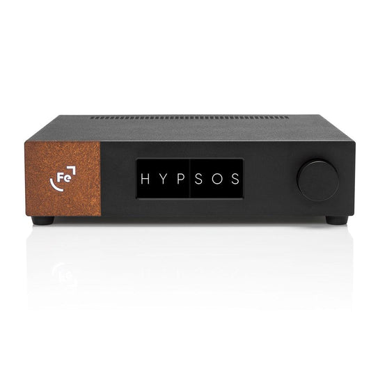
On the rear there is also a four-pin power connector in addition to the standard DC barrel input, which is intended for connection to the HYPSOS power supply. This allows the HYPSOS to sense and correct the supply voltage on the PCB of the OOR itself, rather than at the termination of the power cord.

Opening up the amplifier we see a fairly busy PCB design, a result of the in-house discrete opamp approach Ferrum has taken in contrast to other products which either use ready-made opamp ICs (chips), or those using simpler topologies like many Class A amps, which can get away with using very few components in many instances.

The amplifier is fully balanced and differential. Incoming single ended signals are immediately converted to balanced signals rather than just using a single ended signal path, and as well as the headphone outputs themselves, the OOR also has both single ended and balanced preamp outputs for use with other amplifiers or as part of a two-channel listening system. Whilst compact and running only mildly warm when idle, consuming just 15W, when the situation demands it, the OOR can supply up to just under 9W into 32 Ohms and retains very low distortion for the first 7W or so as well. As to how it sounds, have a look at the video review below to find out!
Measurements
Measurements Include:
- THD+N (SINAD)
- Bandwidth
- THD+N vs Frequency
- Power
- Output Impedance
- CMRR (Common Mode Rejection Ratio)
- Power On/Off Behaviour (Safety Test)
- Volume Matching vs Level of Attenuation
- Noise Level
- Intermodulation Distortion (IMD)
- Dynamic Intermodulation Distortion (DIM)
- Crosstalk
- Multitone
- Square Wave Output
Additional measurements and test information available in the full report
Tests conducted with standard 4V line level XLR input, and tested at 4V/Unity-Gain output, 700mV (Headphone Level) output, and 50mV (IEM Level) Output.
Test Setup
- Audio Precision APx555 B-Series analyzer
- Measurement setup and device under test are running on regulated 230V power from a Furman SPR-16-Ei
- OOR was warmed up for 12 hours prior to testing
- Medium gain used unless otherwise specified
- Tests shown are with a 32Ω load unless otherwise specified
- Exact analyzer/filter configurations for each measurement are detailed in the full reports
- CH1 (Blue) = Left, CH2 (Red) = Right
Full Measurement Reports
THD+N / SINAD
1khz Sine, 4V input, 4V output (300Ω Load):

114dB THD+N here.
With 4V unity gain, distortion is incredibly low, as is overall noise. The main limitation here is actually just interference from the transformer in the HYPSOS itself. The measurements in this post are mostly done with the OOR/HYPSOS stacked as that’s how I believe most people will be using it. However if you do have spare desk space you can eliminate this interference by having the OOR/HYPSOS side by side instead of stacked:
1khz Sine, 4V input, 4V output (300Ω Load, OOR/HYPSOS not stacked):

As shown, having the units side by side does get rid of the transformer interference, however it’s so low, and at lower frequencies where our hearing is vastly less sensitive, that you should not worry about this and should not be concerned about stacking the units. THD+N is only altered by a couple dB and it does not affect any other areas of performance.
1khz Sine, 4V input, 4V output (32Ω Load):
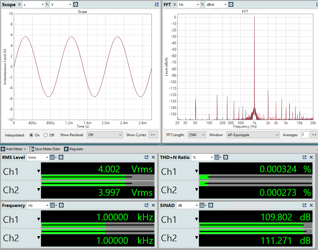
Distortion increases a small amount when the load becomes more difficult, as is typical with many amps, though still does very well, and if we run our ‘2W @ 32 Ohm’ test we can see that performance still holds up excellently.
1khz Sine, 4V input, 8V / 2 Watts output (32Ω Load):

Demanding loads and situations are no challenge.
1khz Sine, 4V input, 700mV output (Headphone Level, 32Ω Load):
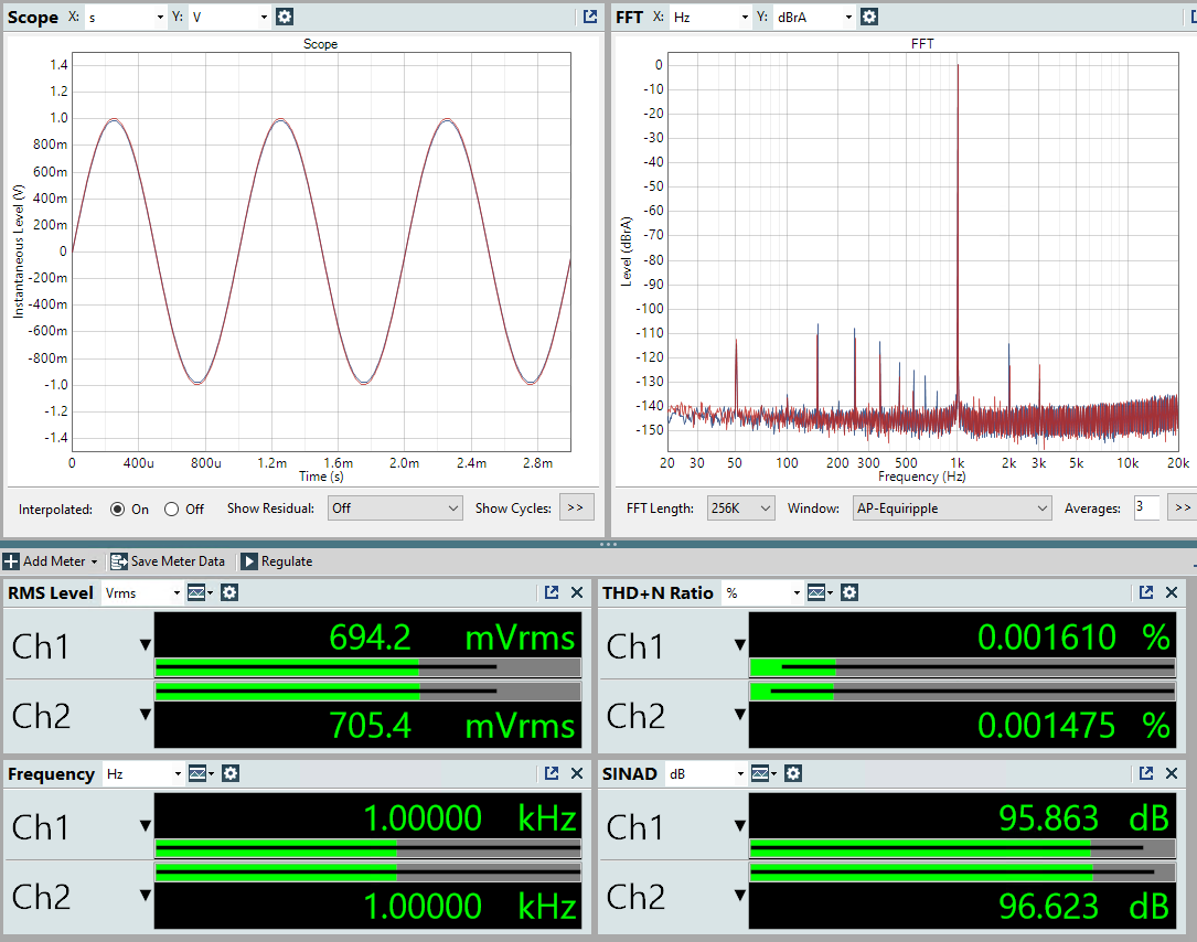
1khz Sine, 4V input, 50mV output (IEM Level, 12Ω Load):

Whilst the noise floor is the limitation here, and it’s not as quiet as some more IEM focused products, the available dynamic range when in use with IEMs is still very good. Additionally, the excellent volume channel matching (shown later in this post) means that even at very low levels you should see almost no channel imbalance. So as well as handling difficult headphones with ease, the OOR should comfortably run IEMs and sensitive headphones too without issue.
1khz Sine, 4V input, 4V output (Preamplifier XLR Output):
 The preamp outputs are also very clean.
Bandwidth
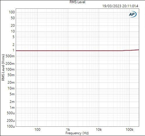
The OOR has a very wide bandwidth and does not attenuate ultrasonic content.
THD+N vs Frequency (96khz capture bandwidth)
(96khz bandwidth used on the analyzer. Don’t compare this directly to standalone audible band THD+N measurements as the measurement setup is not the same.)
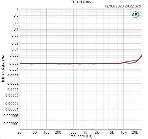
THD+N remains almost entirely flat for the 20hz-20khz audible band. There is no significant rise at higher or lower frequencies.
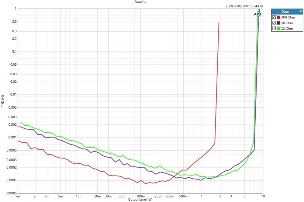
Power
32Ω: 8.5W
300Ω: 1.9W XXX
THD vs Measured Level in dBV (Output voltage):

The OOR shows some change in distortion as the load gets more difficult (lower impedance) and pulls more current, but still retains low distortion to very high output levels.
THD vs Measured Level in Watts:
Output Impedance
XLR (Balanced): 0.3 Ω
6.35mm (Single-Ended): 0.15 Ω
XLR Pre-Out: 44 Ω
RCA Pre-Out: 22 Ω
(Output impedance vs Frequency graphs will be provided at a later date, I am currently waiting for Audio Precision to update the utility.)
CMRR
100hz: 58.2dB (HP Out)
1khz: 58.1dB (HP Out)
10khz: 58.0dB (HP Out)
Power On/Off Behaviour
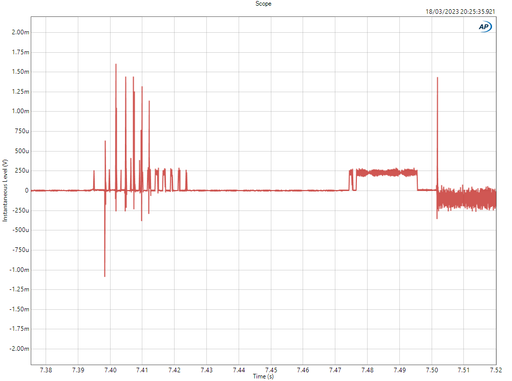
This test shows the output of the device when turned on/off, to check whether the output may put connected headphones at risk. Regardless of what this test may show, please ALWAYS disconnect your headphones when turning any amplifier on/off unless the manufacturer explicitly instructs you to do otherwise.
Turning on (from cold, 300Ω load):
Turning off (from warm, 300Ω load):
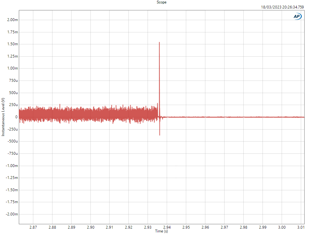
DC Offset is low, and no transient spikes above 2mV when turning off or on. So connected headphones are safe. Always good practice to disconnect headphones before turning any amplifier on/off though.
Volume Matching vs Attenuation
This test adjusts the amplifier to different levels using the volume knob, and shows the level difference in dB between the two channels.
Some amplifiers particularly at lower volumes will have channel imbalance. This test checks how closely the two channels of an amplifier match as volume is reduced.
+5.6dB (Vol maxed, med gain) = 0.02dB
0dB =0.03dB
-6dB = 0.01dB
-12dB = 0.07dB
-26dB = 0.14dB
-32dB = 0.11dB
1dB channel difference reached at -61dB
3dB channel difference reached at -66dB
Volume matching is very good, and will mean that even at very low levels with IEMs for example, you should see almost no channel imbalance.
Noise
Note: For this test the HYPSOS and OOR were unstacked. With the units stacked, some interference from the transformer will be shown as displayed in the graphs at the beginning of the measurement section.
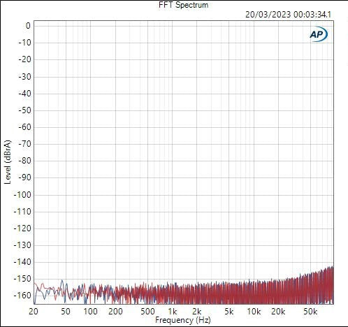
256k FFT, 3 Averages
12.84uV upto 20khz (-109dB referenced to 4Vrms)
21.83uV upto 96khz (-103dB referenced to 4Vrms)
IMD
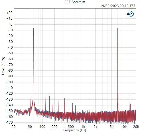
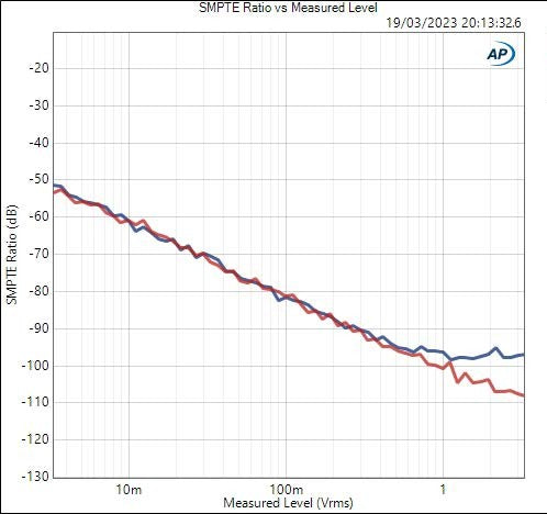
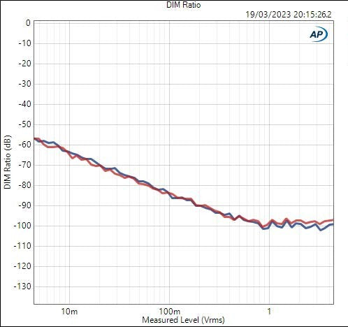
Dynamic IMD (DIM)
Crosstalk
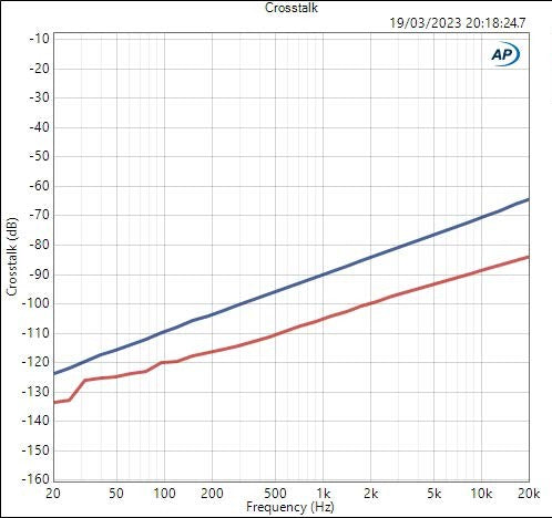
Crosstalk is reasonably low though is dependent on the load. With a 300 Ohm load the maximum crosstalk is -65dB at 20khz whereas with a 32 Ohm load it is -100dB at 20khz. Additionally, there is interestingly some asymmetrical crosstalk here, where leakage from the left channel to the right is higher than leakage from right to left. This could either be due to the ground impedance being different for the left and right channels, or possibly due to the physical layout of the board.
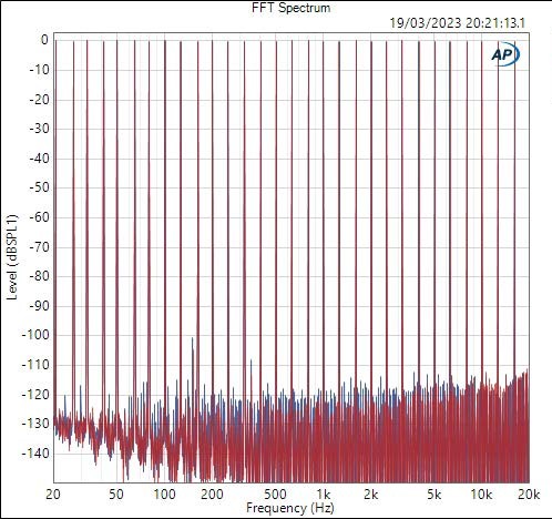
Multitone
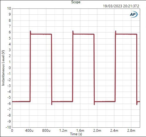
Square Wave Output
