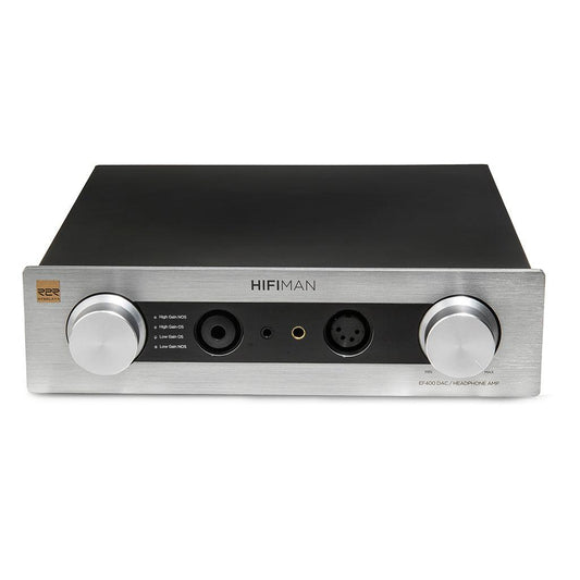
Hifiman EF400 Review & Measurements
Hifiman EF400 Headphone Amplifier and DAC
UPDATE: Hifiman has provided this statement:
"A defect in the EF-400 was discovered last year and affected units were brought back to the factory. Unfortunately a few units ended in consumers hands. Anyone concerned can email us at customerservice@hifiman.com
Introduction
The Hifiman EF400 is a $599 DAC and amp combo unit that offers quite a different design from many of the other products in its price range, most notably the fact that the EF400 uses an R2R DAC design instead of the typical delta-sigma DAC chips found in most other products. R2R DACs are an older technology that has the benefit of being able to convert PCM digital audio natively, unlike delta-sigma DACs which must oversample and modulate the 44.1khz 16 bit audio to a much higher sample rate, much lower bit depth format, often around 22Mhz and 3-6 bits. Whilst R2R DACs typically (though not always) perform objectively poorer than competing delta sigma designs, many listeners swear by the resulting sound they produce, as well as many enjoying the sound of ‘NOS’ or non-oversampling modes that R2R DACs are often capable of.
The EF400 uses Hifiman’s proprietary ‘Himalaya’ R2R design, with a linear power supply and an inbuilt amplifier.

Unfortunately the inputs for the EF400 are rather limited, with the only options being USB type B and type C. This means that you won’t be able to hook the EF400 up to a TV or any other SPDIF source, nor will you be able to use it with an alternative external DAC, though it is always nice to see USB type-C on products.
Review
Measurements
Measurements Index
- THD+N / SINAD
- THD+N vs Frequency
- Power / THD+N vs Output Level
- Low Level Signal Output
- Nyquist Reconstruction Filter / Oversampling
- Noise When Idle
- IMD
- Linearity
- Crosstalk
- Jitter
- Multitone
- Wideband Noise & Distortion
- Volume Matching
- Power On/Off Behaviour (Safety Test)
- Interchannel Phase
Additional measurements and test information available in the full reports
Test Setup
- Audio Precision APx555 B-Series Analyzer
- Neurochrome HP-LOAD Dummy Load
- 100kΩ Input Impedance used unless otherwise stated
- USB Source: Intel PC via intona 7055-C isolator
- Measurement setup and device under test are running on regulated 230V power from a Furman SPR-16-Ei
- EF400 was warmed up for 24 hours prior to testing
- Measurements shown are from the balanced headphone output with a 32Ω load unless otherwise stated
- Measurements shown are using the ‘Low-Gain OS’ setting unless otherwise stated as this produced the best objective results
- Exact analyzer/filter configurations for each measurement are detailed in the full reports
- CH1 (Blue) = Left, CH2 (Red) = Right
Full Measurement Reports
Full Report (Bal Headphone Out 32 Ohm)
Full Report (Bal Headphone Out 300 Ohm)
Results
Dynamic Range (AES17): 99.4dB
SNR: 111.7dB
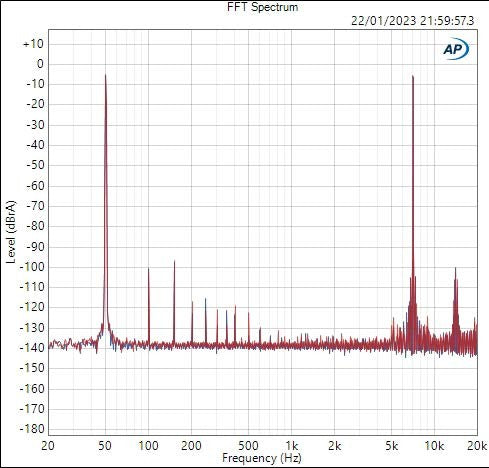
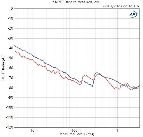
IMD SMPTE: -76.3dB
Noise Level RMS (20-20khz): 15.81uVrms
Noise Level RMS (20-90khz): 20.30uVrms
Noise Level RMS (20-1Mhz): 46.16uVrms
DC Offset: 4.2mV active, 4.0mV idle
Susceptible to intersample overs: Yes
Output Impedance: 9.6Ω
THD+N / SINAD
1khz 0dBFS Sine, 4V output (32Ω):

1khz 0dBFS Sine, 700mV output (Headphone Level, 32Ω):

1khz 0dBFS Sine, 50mV output (IEM Level, 12Ω):

1khz 0dBFS Sine, (DAC XLR Outputs, NOS):
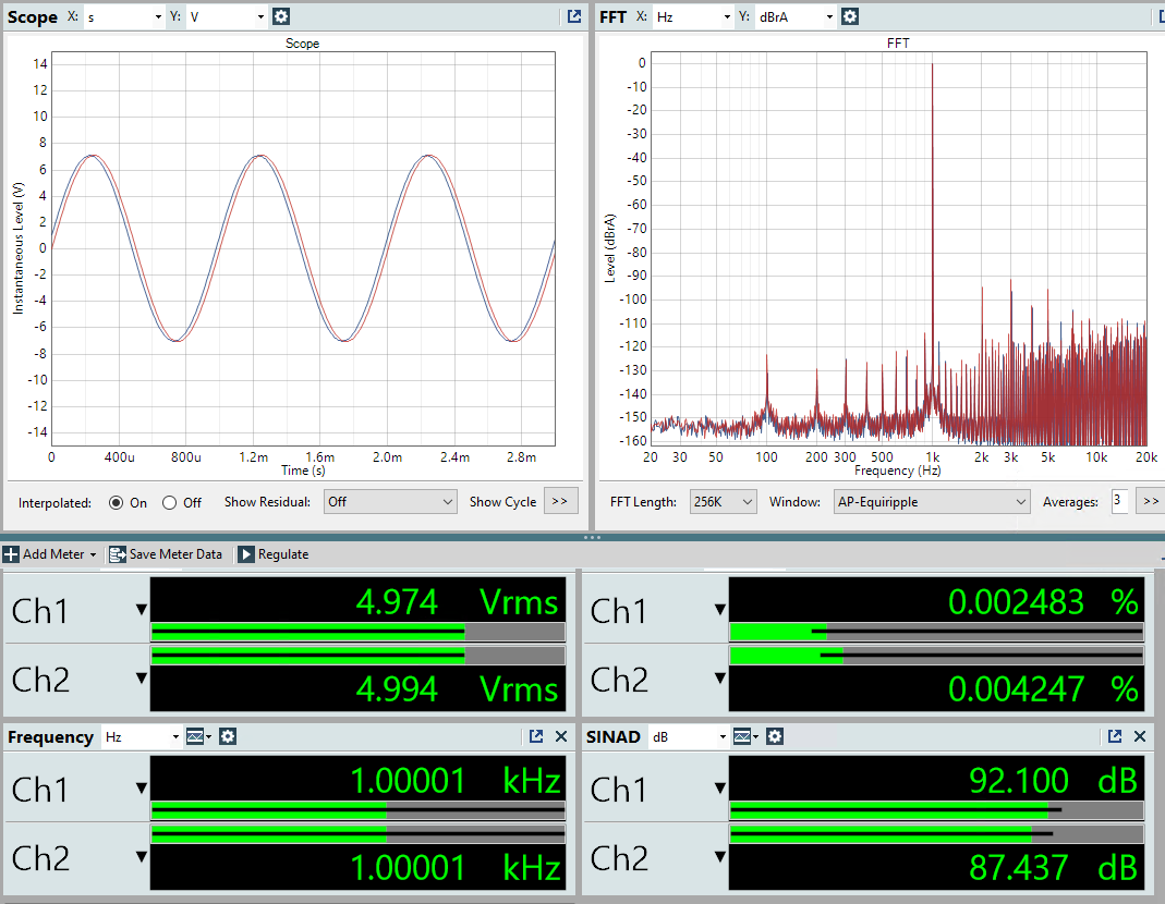
1khz 0dBFS Sine, (DAC XLR Outputs, OS):

THD+N vs Frequency
This test measures the THD+N at different frequencies, which can reveal information about how the device performs in areas other than just 1khz.

Note: a 90khz bandwidth filter is used on the analyzer to capture harmonics above 20khz. Do not directly compare figures here to standalone THD+N results taken with a standard 20khz filter
The THD+N vs frequency on the EF400 is quite U shaped, with a rise not only into the higher frequencies which is not too uncommon, but also a rise into the lower frequencies. This may result in a softer/sweeter subjective sound.
Power / THD+N vs Output Level
This test measures the THD+N at various output levels. This can be useful for DACs, but is also used for amplifiers, where maximum power is typically specified as the maximum output a device can supply before reaching 1% THD.
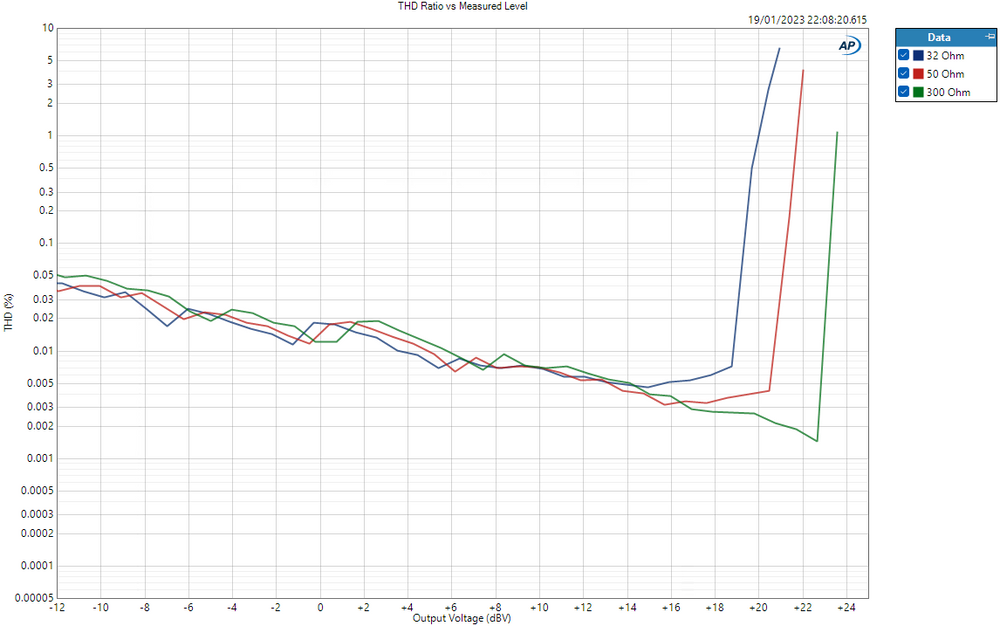
XLR Headphone Out, 32, 50 and 300Ω loads, Voltage in dBV on X-Axis

XLR Headphone Out, 32, 50 and 300Ω loads, Power in Watts on X-Axis
The EF400 does not meet the specified 4.4W power output. Best case I was able to get roughly 3W @ 32 Ohms.

XLR DAC output, 200kΩ analyzer input impedance
Low Level Signal Output
This test puts a very low level signal through the device to check for any unusual behaviour.

-90.31dBfs 24 bit dithered sine
There is some glitching occurring close to the 0 crossing point. Not particularly high in level, but still not ideal.

-90.31dBfs 16 bit undithered sine
Swapping to an undithered 16 bit sine, this glitching gets significantly worse as the DAC holds at the 0 crossing point for longer periods.
Nyquist Reconstruction Filter / Oversampling
White noise at 44.1khz sampling rate is played through device, the result shows us how effectively the oversampling/reconstruction filter removes unwanted content above 22.05khz.

DAC XLR outputs, OS mode, 44.1khz white noise played through device

DAC XLR outputs, NOS mode, 44.1khz white noise played through device
Noise When Idle
This test simply shows an FFT of the output of the device when idle/not playing anything.

IMD
This test plays a 60hz and 7khz tone through the device. Intermodulation distortion is the unwanted content that shows up around the 7khz tone as a result. This type of distortion is not harmonic distortion, and is considerably more audible.
Linearity
This test plays a 1khz tone through the device, and steps down the level in small increments. Linearity measures how accurately the actual output of the device reflects the intended output. For example, if the level was stepped down by 20dB, but the output of the device was 19.7dB quieter, there is a 0.3dB nonlinearity, which would show as a 0.3dB rise on the graph.

Bandpass filtered, this is measuring only the accuracy of the 1khz tone itself

No bandpass filter, this factors in noise into the result
Crosstalk
This test plays a signal through one channel of the device, and measures how much of it leaks through to the other channel.

Jitter
This test uses a ‘J-Test’ signal, which shows distortion caused by variation/errors in timing. Even if all data is correct and other distortions are very low, timing inconsistency can cause inaccurate output from a DAC. Please note: the J-Test is a workaround to show a time-domain error on a frequency domain FFT. Please do not directly compare levels of distortion here to other types of distortion.

DAC XLR Out, USB input, 44.1khz

DAC XLR Out, USB input, 48khz
The results of the J-Test on the EF400 were unusual. The floor shows as quite high and flat which usually indicates that the output is being interrupted for a very small duration. This occurred every time I ran the test.
This is most likely caused by the low level glitching at the 0 crossing point shown earlier.
Multitone
This test plays 32 tones through the device to test behaviour with a very complex waveform. It does not usually show anything that would not be shown on a THD+N vs frequency graph, but is a useful check to make sure there is no unexpected behaviour.

Wideband Noise & Distortion

Idle

-3dB 1khz sine playing
Volume Matching
A signal is played through the device. The volume knob is then adjusted to different levels, and the difference in volume between the two channels is noted. The lower the result the closer the channels are matched. Some devices with lower quality potentiometers will show larger channel imbalance particularly at lower levels which can present a challenge for quieter listeners and/or IEM users.
0dBV (1Vrms) = 0.40dB
-10dBV (0.32Vrms) = 0.44dB
-20dBV (0.1Vrms) = 0.34dB
-30dBV (32mV, quiet IEM level) = 0.9dB
Power On/Off Behaviour (Safety Test)
This shows the output of the device when switched on/off. A large transient, or a significant DC offset may pose a risk to headphones if they are left connected whilst the device is switched on or off.

Turning off from warm

Turning on from cold
Generally well handled, a slight transient upto 10mV when turning on but this is extremely unlikely to pose any risk to headphones. May not wish to turn it on with IEMs connected and in your ears though.
Turning off the device, it simply goes from the static 4mV DC offset to 0.
Regardless of what this test shows, we would always recommend you disconnect your headphones before turning a device on or off.
Interchannel Phase
A device should always be outputting the left and right channels at the same time, however in some instances, DACs may have a slight offset between the left and right channels due to a design flaw.
Below is the interchannel phase for the EF400:

You can see that in both modes, though significantly more so in NOS, there is a phase offset between the two channels, meaning for high frequency content, the outputs can be almost entirely out of alignment:

20khz sine
This may have an effect on perception of direction and spatial presentation, and in more drastic instances, could potentially cause discomfort for listeners.
But why is this occurring? Well, it’s actually to do with how products with a dual-DAC design process the I2S signal that controls them. If not done properly, the two DACs can end up converting the streams for the left and right channels at slightly incorrect times.
DACs use I2S internally, that’s the language which the USB implementation feeds to the DAC itself, and it is composed of at least four lines:

Example of a typical I2S connection
There are at least two lines for data (labeled ‘SD’ or serial data in the image above), which are differential, hence the symmetrical look. And there is also a ‘bit clock’ line (labeled SCK above), which is what the DAC uses to keep everything in time.
But what we are most interested in here is the middle ‘word select’ or ‘L/R clock’ line. This clock signal is intended to tell the DAC “Hey! This bit of data is for the left channel”, as the left and right samples can’t be provided simultaneously. You have to provide one then the other and the DAC needs a way of knowing which is which.
In the instance above, when the word clock goes down, that tells the DAC that everything from the next bit clock cycle onwards is for the left channel, and once the word clock moves up, that tells the DAC that everything from the next bit clock cycle onwards is for the right channel.
So what’s the issue? Well, you’re feeding the DAC the left channel info first, then the right after. But these two bits of information are supposed to be converted at the same time. So usually, with a single DAC, or a properly designed dual-DAC, the DAC/channel which is receiving data first will take the left channel data, then wait for the full word clock cycle to finish, then output. Whilst the other can receive data and then output immediately. This results in both outputting the respective left and right samples at exactly the same time.
However if you have a dual DAC solution and do not implement this waiting period, meaning the left DAC converts the data as soon as it is received, and so does the right, then you’ll have one DAC converting the left channel data one sample early. This mismatch in timing causes the outputs to be out of phase. One 44.1khz sample too early is a 0.0226ms time difference, which for 20khz is 163 degrees, exactly what we see on the EF400 in NOS.
The reason the EF400 shows less of a phase difference in OS is because the sample rate is higher, and so this time difference is reduced. If you have the same issue described above, but instead of 44.1khz, that data is oversampled to 356khz, then you now have a time difference of 0.0028ms between samples, resulting in a phase difference of only 20 deg at 20khz.
Hopefully this is an issue that Hifiman can fix with a firmware update.
